Avionics and embedded systems project
Custom UAV Flight Controller & Avionics Platform
A ground-up flight-control and avionics platform for a fixed-wing UAV, designed to scale into a future VTOL tilt-rotor aircraft.
Overview
The project centers on building the underlying flight-control electronics, firmware architecture, and interfaces instead of relying entirely on an off-the-shelf controller. Flight-critical control stays on a dedicated MCU, and a redundant flight controller architecture is used to preserve reliability in adverse conditions.
Current focus
- Fixed-wing UAV first for controlled system validation
- Flight-critical loops on STM32H723 with deterministic timing
- Redundant inertial sensing on independent SPI buses
- Modular interfaces for navigation and payload expansion
- Companion-computer integration for non-real-time compute
Where the avionics system stands
Schematic capture is complete across every subsystem: MCU core, redundant sensing, power tree, USB, and the full I/O breakout. The flight-controller PCB has been placed and routed as a four-layer board. I cross-checked STM32H723 peripheral assignments against the datasheet and CubeMX to allow PWM, communication buses, USB, GPIO, and SWD to function in tandem. The next stage in the process is hardware bring-up and software testing.
- +Full schematic capture across MCU, sensors, power, USB, and I/O
- +Timer and peripheral map validated against datasheet and CubeMX
- +First flight-controller PCB placed and routed on four layers
- +Test points and SWD debug header grouped for bench work
- +Next: board fabrication, assembly, and power-on bring-up
- +Then: sensor calibration and closed-loop control on the bench
Flight-controller board
The board packs the MCU, both IMUs, the barometer, the regulated power stage, USB-C, dual CAN transceivers, and every servo/UART/GPIO connector into a compact four-layer outline with mounting holes on a standard pattern. Connectors sit on the board edges so harnesses route cleanly once it is mounted in an airframe.
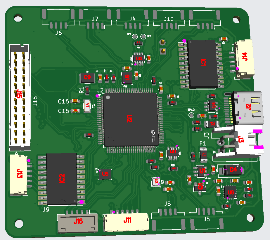
Populated 3D render
Assembly view with the STM32H723 (U2), CAN transceivers, USB-C and micro-USB, FFC/FPC edge connectors, and the JST-GH connector bank.
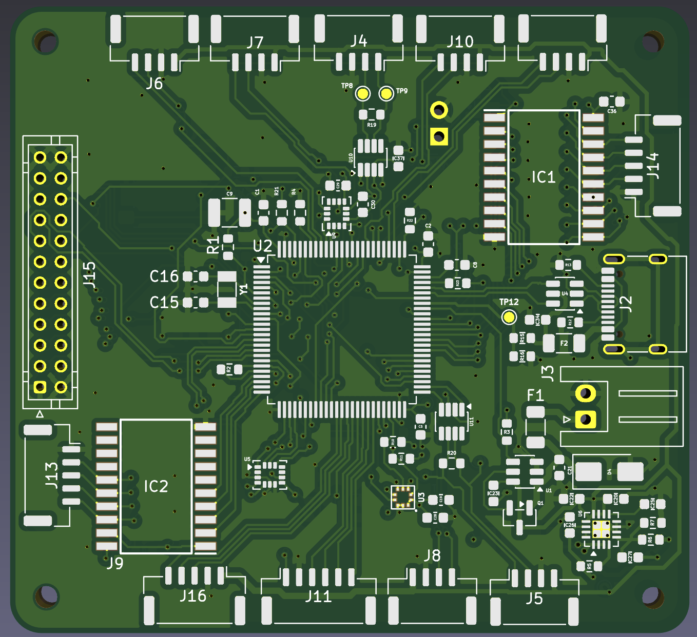
Top-layer layout
MCU escape routing, decoupling under the package, and the analog/sensor corner kept away from the switching regulator.
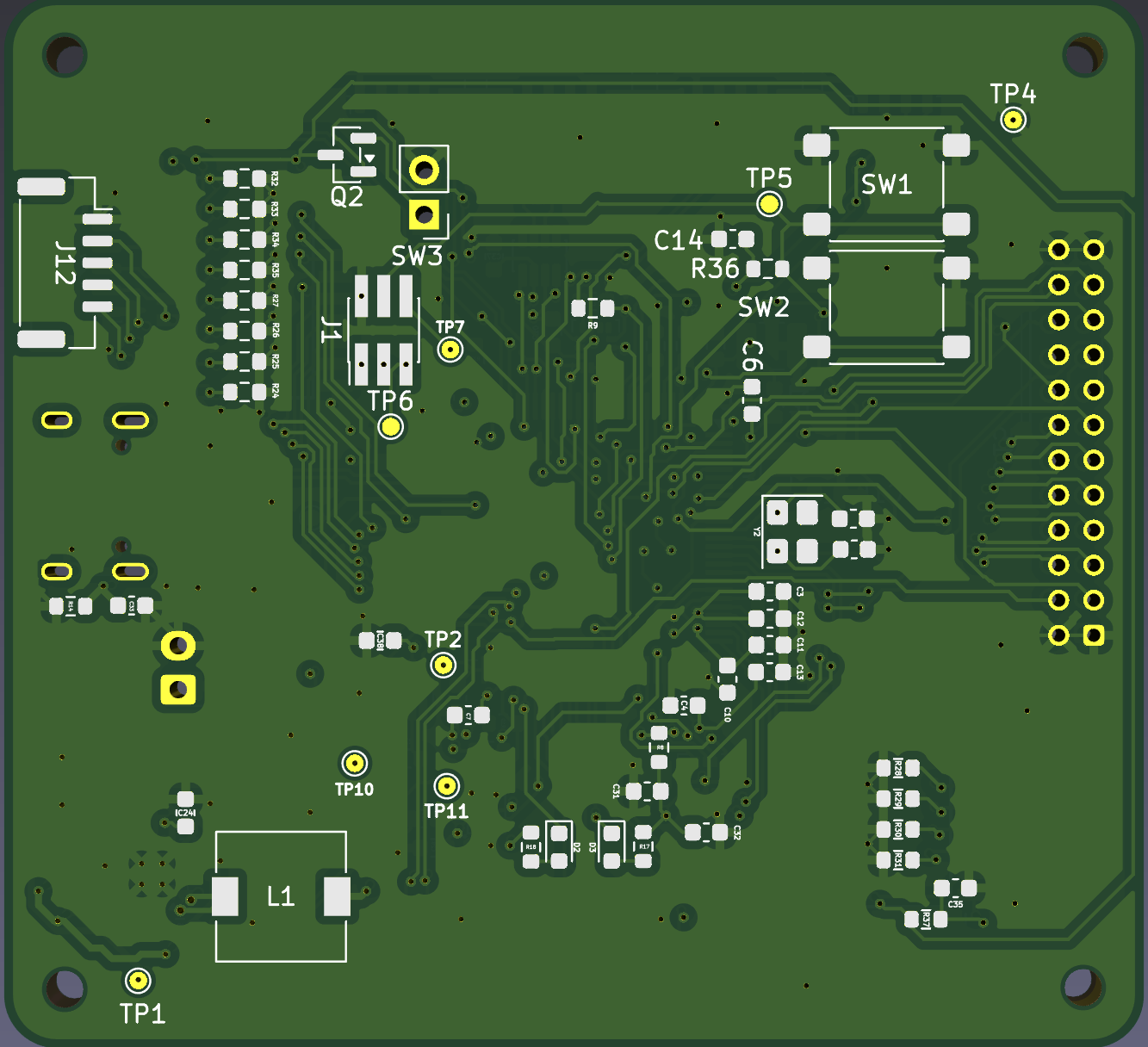
Bottom-layer layout
Buck inductor and power components, safety-switch buffers, and the debug/test-point cluster grouped for bench access.
Avionics subsystem design
Each subsystem was captured as its own schematic sheet so interfaces, protection, and power domains stay explicit and reviewable.
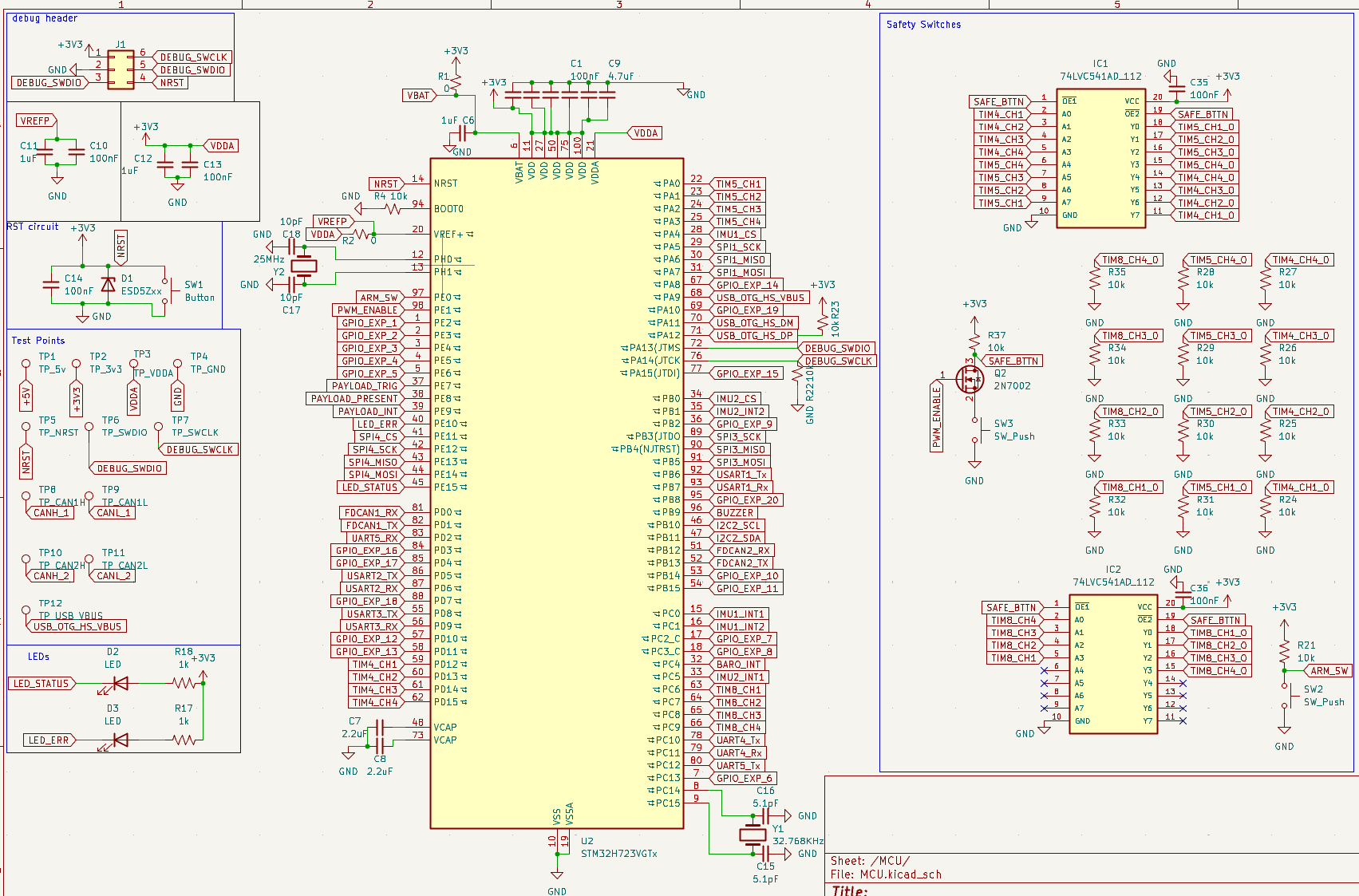
MCU core and debug
An STM32H723VGT runs the deterministic flight loop and acts as the central avionics interface. The sheet covers the 25 MHz HSE and 32.768 kHz RTC crystals, boot and reset handling, a standard SWD debug header, status and error LEDs, and a bank of test points for the 5 V, 3.3 V, VDDA, CAN, and USB nets.
Redundant inertial and barometric sensing
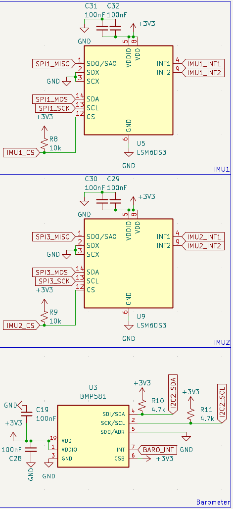
Two LSM6DS3 six-axis IMUs sit on separate SPI buses (SPI1 and SPI3) with independent chip selects and interrupt lines, so a single bus or sensor failure does not take out attitude sensing. A BMP581 barometer on I2C2 provides altitude, with its interrupt routed back to the MCU.
Power tree and protection
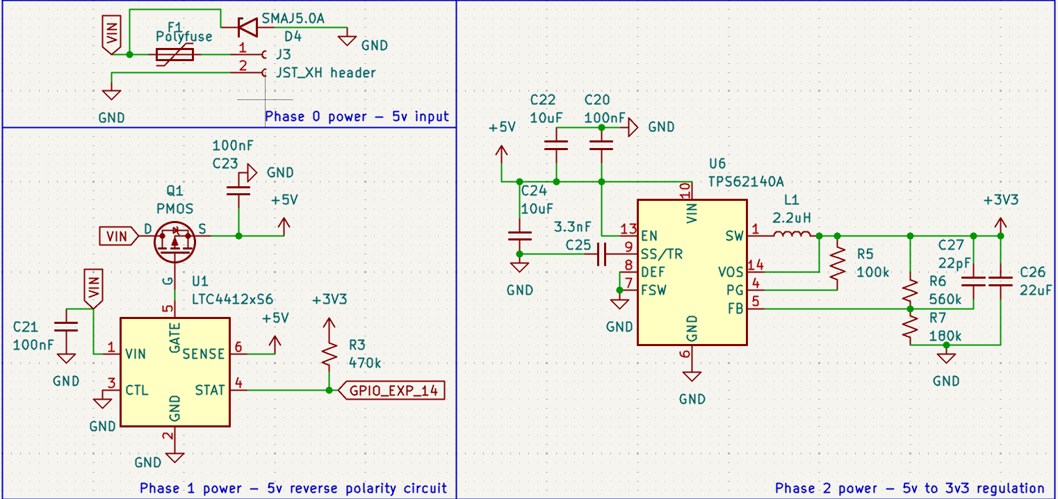
The board takes a 5 V input through a polyfuse and a 5 V TVS for over-current and transient protection, then a P-channel MOSFET driven by an LTC4412 ideal-diode controller for near lossless reverse-polarity protection. A TPS62140A step-down converter generates the 3.3 V rail, with a separately filtered VDDA feed for the MCU analog supply.
USB-C interface
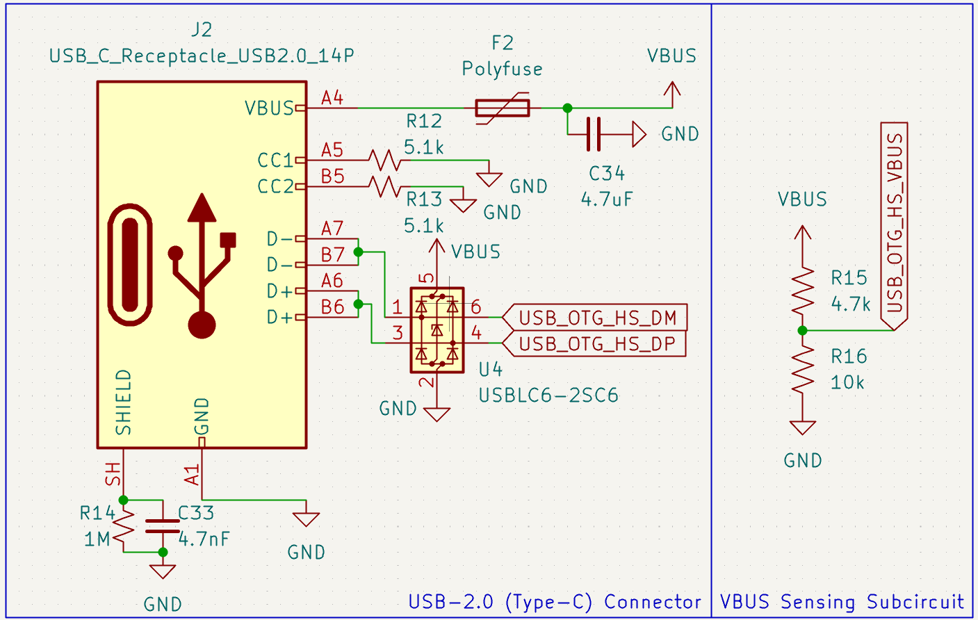
A USB 2.0 Type-C receptacle handles firmware updates and console access. It includes 5.1 k CC resistors for sink detection, a USBLC6-2SC6 for ESD protection on the data lines, a polyfuse on VBUS, and a divider that lets the MCU sense whether VBUS is present.
Communications, I/O, and expansion
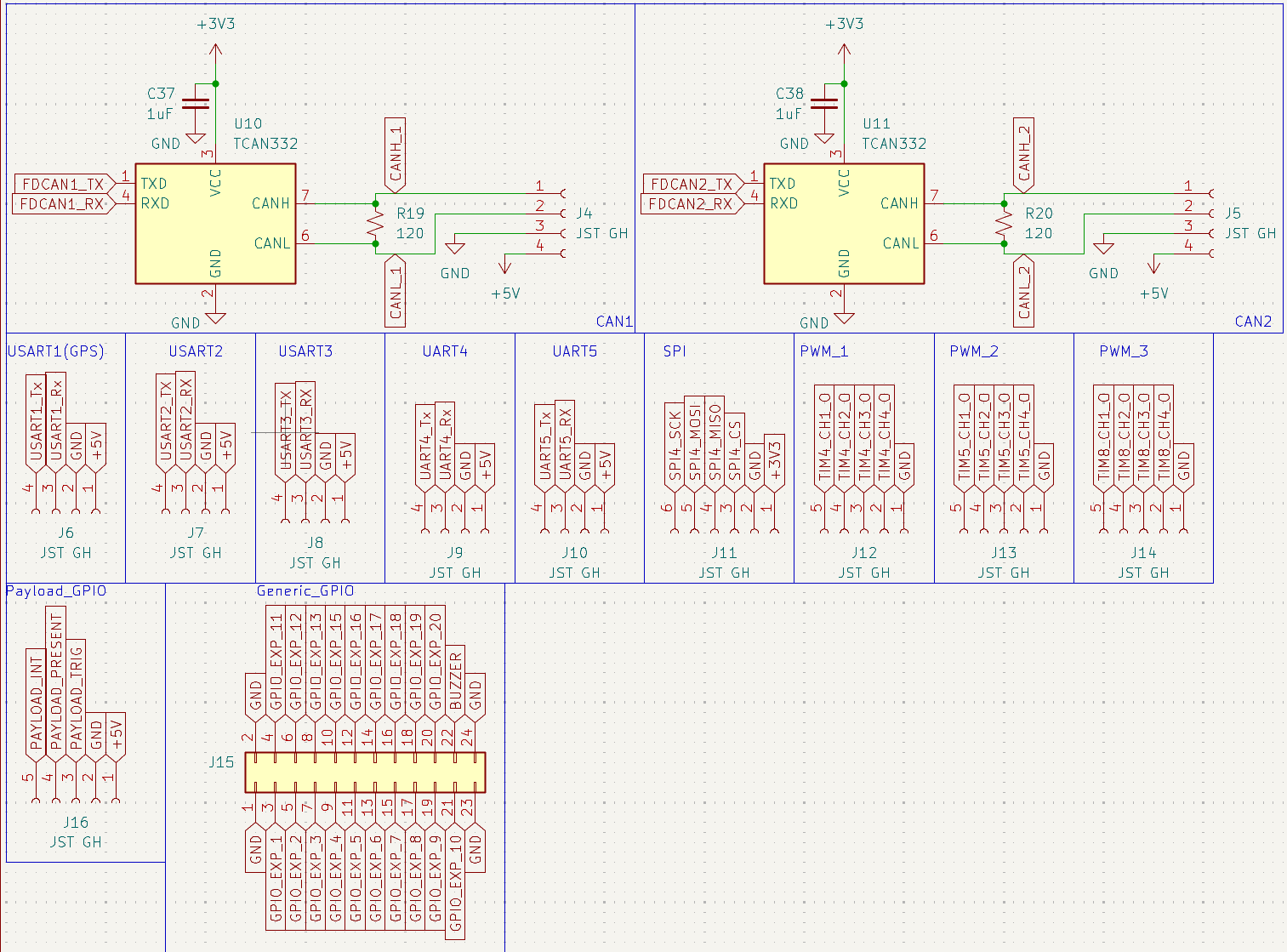
Two isolated-friendly CAN FD channels use TCAN332 transceivers with on-board 120 Ω termination on JST-GH connectors. Five UART headers break out (USART1 reserved for GPS), along with an external SPI header, three timer-driven PWM banks, a 24-pin generic GPIO expansion header with a buzzer output, and a dedicated payload GPIO connector for trigger, present, and interrupt lines.
Actuator output and safety interlock
Twelve PWM channels are generated from three independent timers (TIM4, TIM5, TIM8), split into three connectorized banks for ESCs and servos. Every channel passes through a pair of 74LVC541 buffers that are only enabled when the arming line and a physical safety switch agree, so a firmware fault cannot drive the actuators on its own.
Development strategy
Phase 1: fixed-wing validation
Validate avionics reliability, sensor behavior, communications, and control algorithms on a simpler aircraft architecture.
Phase 2: VTOL extension
Reuse the same avionics foundation for multi-motor and tilt-rotor control once the core flight stack is proven.
Project scope
- +Embedded real-time firmware
- +Custom PCB and interface design
- +Power electronics and domain separation
- +Avionics and control-system architecture